leaderboard 1

Thursday 3 June 2021

Where are the fuse boxes on subaru - 1996 Subaru Impreza

 subaru impreza fuse box


There are two fuse boxs: under the dashboard on the drivers side on the extreme left side and there are fuses in the engine compartment on drivers side including: relay switches, signals and lighting.Where are the fuse boxes on subaru - 5_19_2012_9_30_43_am.jpg

keurig 2.0 touch screen power button not working

 Keurig  coffee maker Troubleshooting:


The problem with the touchscreen not responding, is caused by dirt/coffee residue, getting under the bezel around the screen. Sometimes a tissue soaked in Windex, then polished with a dry one , will temporarily remedy this. The only permanent fix is to disassemble the head, remove the lcd screen and clean it thoroughly, as well as under the bezel.


If your Keurig 2.0 display is blank, try unplugging the brewer and plugging it back on. See if the issue is resolved. If your Keurig 2.0 touch screen is still cold towards you, get ready for some troubleshooting.


Step 1: Plug in your Keurig 2.0. The power icon should be at the bottom left of the display.

 If nothing shows, follow our section ‘My Keurig Won’t Turn On’.

If you can see the Power button, turn it on and proceed to Step 2.

Step 2: Go to “Menu” and proceed to set the clock.

Step 3: Navigate yourself through the “Menu” and try to set all the menu options.

Step 4: When you reach the “Lift to Begin” screen, lift the handle then lower it down.

Step 5: If the brewer shows signs of beginning to start a brew, your troubleshooting is successful.

igloo ice maker ice full sensor

 Igloo ice maker icefull light stays on

If the igloo ice maker icefull light stays on, that means 


The hard water had covered the infrared source and/or receiver. They are opposing black and transparent 3mm circles on the left and right wall when you look inside your icemaker. They are supposed to detect if ice cubes pile up so high that they disrupt the direct liner of view between those 2 dots.
Just clean them with a wet acidic solution to clean of the hardness, e.g. use vinegar or lemon juice.This process will help to get icefull light off.

Also you can try this simple trick if the above process is not helping

1. turn machine on . 2. press the select button for 10 sec. then 3. press the power button for 10 sec. and then turn off the machine and unplug it for 6 hours.


Make sure the small emitter that sends a beam through the ice bucket to read ice height is not blocked or dirty.

Monday 31 May 2021

toyota tacoma fuse box

TOYOTA TACOMA FUSE BOX 

EFI fuse under the hood


Toyota Tacoma (2005 – 2008) – fuse box diagram

Year of production: 2005, 2006, 2007, 2008
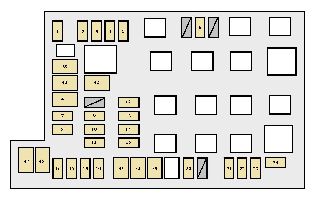
Engine compartment

Toyota Tacoma mk2 - fuse box - engine compartment
Toyota Tacoma mk2 – fuse box – engine compartment

Instrument panel

Toyota Tacoma mk2 - fuse box - instrument panel
Toyota Tacoma mk2 – fuse box – instrument panel

Fuses (type A)

FuseAmpere rating [A]Circuit
1A/C10Air conditioning system
2FR FOG15Front fog lights
3TOWING TAIL30Trailer lights (tail lights)
4STOP10Stop lights, high mounted stop light, vehicle stability control system, anti- lock brake system, shift lock system, multiport fuel injection system/ sequential multiport fuel injection system, towing converter
5OBD7,5On- board diagnosis system
6EFI NO.210Multiport fuel injection system/sequential multiport fuel injection system
7TOWING BRK30Trailer brake controller
8BATT CHG30Trailer sub battery
9TOWING30Towing converter
10TRN- HAZ15Turn signal lights, emergency flashers, meter and gauge
11RADIO NO.230Audio system
12HEAD (LO RH)10Right- hand headlight (low beam)
13HEAD (LO LH)10Left- hand headlight (low beam), front fog lights
14HEAD (HI RH)10Right- hand headlight (high beam)
15HEAD (HI LH)10Left- hand headlight (high beam), meter and gauge
16ETCS10Multiport fuel injection system/sequential multiport fuel injection system, electronic throttle control system
17ALT- S7,5Charging system
18EFI20Multiport fuel injection system/sequential multiport fuel injection system
19HORN10Horn
20A/F HEATER15Multiport fuel injection system/sequential multiport fuel injection system
21ECU- B7,5Wireless remote control system, air conditioning system, multiplex communication system, engine immobilizer system, meter and gauge, clock, front passenger occupant classification system
22DOME7,5Interior light, personal lights
23RADIO NO.110Audio system
24STA7,5Starting system, multiport fuel injection system/sequential multiport fuel injection system, meter and gauge, clutch start cancel switch
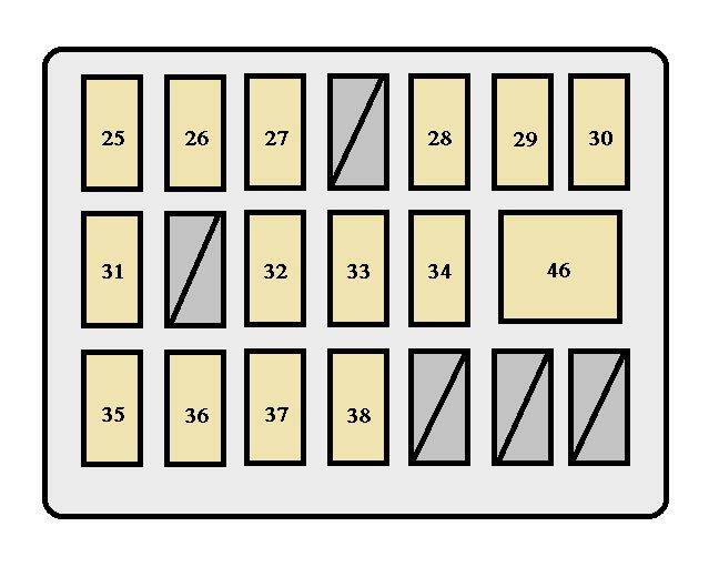
25IGN15Multiport fuel injection system/sequential multiport fuel injection system, engine immobilizer system, anti- lock brake system, traction control system, vehicle stability control system, SRS airbag system, front passenger occupant classification system
26GAUGE7,5Meter and gauge, emergency flashers, front passenger’s seat belt warning system
27TAIL10Tail lights, license plate lights, parking lights, multiport fuel injection system/sequential multiport fuel injection system, front fog lights, instrument panel light control, illuminations
28ACC7,5Shift lock system, outside rear view mirrors, audio system, power outlets
29PWR OUTLET15Power outlets
30DR LCK20Door lock system
31IG1 NO.210Anti- lock brake system, vehicle stability control system, stop lights, charging system, multiport fuel injection system/sequential multiport fuel injection system, air conditioning system, instrument panel light control, clutch start cancel switch, rear differential lock system, power outlets
32IG110Back- up lights, air conditioning system, passenger airbag manual on- off switch, shift lock system
33P RR P/W20Rear passenger’s power window (right side)
34P FR P/W20Front passenger’s power window
35WSH10Wipers and washer
36D RR P/W20Rear passenger’s power window (left side)
384WD20Four- wheel drive system, rear differential lock system
39WIP30Wipers and washer

Fuses (type B)

FuseAmpere rating [A]Circuit
40J/B50“TAIL”, “AC SKT”, “DR LCK”, “D FR P/W”, “D RR P/W”, “P FR P/W”, “P RR P/W”
41AM150“ACC”, “IG1”, “IG1 NO.2”, “WIP”, “WSH”, “4WD”, “STA”
42HEATER50“A/C”, air conditioning system
42ABS NO.150Anti- lock brake system, vehicle stability control system
43AM230“IGN”, “GAUGE”, multiport fuel injection system/sequential multiport fuel injection system
44A/PUMP50Multiport fuel injection system/sequential multiport fuel injection system
45ABS NO.230Anti- lock brake system, vehicle stability control
46D FR P/W30Power windows

Fuses (type C)

FuseAmpere rating [A]Circuit
47AC SKT100Cigarette lighter, power outlets

Fuses (type D)

FuseAmpere rating [A]Circuit
48ALT120 (without towing package)“AM1”, “AC SKT”, “HEATER”, “FR FOG”, “STOP”, “OBD”, “J/B”, “TOWING TAIL”, “TOWING BRK”, “BATT CHG”
140 (with towing package)

WARNING: Terminal and harness assignments for individual connectors will vary depending on vehicle equipment level, model, and market.

honda fuse box diagram

 Where is fuse box located in honda


Fuses, located in-between the battery, are the electrical components your car draws power from. It's important to know where the fuses are located and what each fuse does, so that if you ever have a problem you know where to start looking. Always start the diagnosis of an electrical problem with its fuse because they are easy to test and pretty cheap to replace.

Honda  Component Breakdown
Interior Fuse Box
The interior fuse box is located underneath the dashboard on the driver's side. The lid is clipped in. To remove it, swing the lid down and pull it out.


Interior Fuse Box

Driver's side fuse box.


The interior fuse panel (Figure 1a) is located under the dash (Figure 1b). The table in Figure 1c contains the fuse, the rating, and what the fuse does. For example, if your radio stopped working, you'd need to test fuse number 23 and replace it with a new 15 amp fuse if found to be faulty. Because interior fuses commonly fail, it is recommended to keep a pack with an assortment of different amperage in the glove compartment.

Under the Hood Fuse Box

The fuse box under the hood is located next to the battery in the engine compartment.


The diagram in Figure 2a is the layout of the fuse box located under the hood. Figure 2c gives the amperage and what the fuse—in that location—controls. These fuses are less likely to blow than the ones inside the car. That said, it'll also be less likely that there'll be a spare handily available in the event that one does. If one of these fuses does blow, it's usually a sign that there is something else wrong that caused it to fail in the first place.

Honda Civic (1996-2000) Component Breakdown
Interior Fuse Box
Figure 3a is the layout of the interior fuse panel (located under the dash), while Figure 3b is a table containing the fuse number, the rating, and what that fuse does. If the radio stopped working, for example, the next step would be to test fuse number 23 and replace it with a new 15 amp fuse if it's faulty. Interior fuses fail more frequently than under the hood fuses, which is why it is recommend keeping an assortment pack with different amperage fuses in the glove compartment.
Diagram of the fuse box under the hood.


Under the Hood Fuse Box
Figure 4a is the layout of the fuse panel, which is located under the hood, while Figure 4b gives the amperage and what that fuse—in that location—controls. These fuses are less likely to blow and are larger fuses than ones inside the car, so it's less likely you will have a spare in the even one does. In addition, if one of these fuses does blow it's usually a sign that there is something else wrong that caused it to fail in the first place.


Engines VIN or serial number?

Location of engine vin serial number The vehicle identification number (VIN) is located on the left side rear of the engine block (1) and is typically a nine digit number stamped or laser-etched onto the engine at the vehicle assembly plant. •The first digit identifies the division. •The second digit identifies the model year. •The third digit identifies the assembly plant. •The fourth through ninth digits are the last six digits of the VIN. 

engine vin number location


Monday 6 June 2016

95 mustang leaking coolant behind water pump.

Coolant Leaking Behind Waterpump


95 mustang v6 leaking coolant behind the new water pump. worse when turned on. does not appear to be the pump or any hoses.

Solution:
If the leak is behind the water pump , then either the new water pump gasket is leaking or the timing cover from the timing chain that the water pump bolts to is leaking and the gasket between the timing cover and the engine block.

waterpump coolant leaking

A couple of the water pump bolts are actually studs that go through the timing cover to the engine block. When the nuts are loosened, the timing cover also loosens. If the gasket for the timing cover is close to failing, it will start to leak. The reason it doesn't leak much with the engine off it because the water pump is not running and no real pressure is on the system. When the engine is running, the cooling system builds up pressure, usually 16 psi and it will push through a weak gasket.

I think it is just in need of a new gasket at 151000 miles. The bolts will really go in one way and the nuts on the studs will tighten up when in the correct place. If you removed the studs, then the gasket is in need of replacement.
--------

PROBLEM 2:
Now it idles smooth. Seems to have all the air out of the coolant lines. BUT when I drive it, it runs with the temp gauge to the red, then cools off to the center, then back to almost the red. The only time the heat kicks out hot air (heat on the whole time) is when it gets to the red and immediately goes to the center. At this time, it runs rough. After it cools off, it idles great, runs great for a short while. Think it is a head gasket?

There should be a bleeder cap bolt located on top of the engine near the front of the intake.It is right above the thermostat on the intake manifold.

thermostat


There should be a bleeder cap bolt located on top of the engine near the front of the intake.It is right above the thermostat on the intake manifold.
graphic
When the engine is cold, remove the bleeder bolt and fill the radiator with coolant till the coolant comes out the bleeder opening. Then reinstall the bleeder bolt and start the engine. Let it warm up and then loosen the bleeder bolt, do not remove it, just loosen it and let some coolant come out and then close the bleeder. Top the coolant off and drive the Mustang.
The problem you have is an air pocket in the cooling system.

Thermostat Operation:
The automotive thermostat is a temperature controlled on and off valve. When the temperature rises to a predetermined temperature, the thermostat opens up to allow the engine coolant to flow through the cylinder block and the radiator. This flow is crucial to maintain optimum operating temperature for fuel efficiency, enhanced driveability, and engine protection. The coolant flow is reduced when the engine is cold, and the flow is increased when the engine is hot. Contrary to popular opinion, operating the vehicle without the thermostat doesn't make the engine run cooler. It will actually run hotter because there isn't a thermostat to slow the coolant flow. This means the coolant doesn't stay in the radiator long enough to dissipate its heat.

Coolant Temperature Sensor Operation:
This sensor monitors the temperature of the engine and sends that information to the engine control computer to regulate the amount of fuel needed. More fuel is needed if the engine is cold; less if it's hot. If the temperature is extreme, the signal will be sent to the temperature gauge as a visual indicator of overheating and imminent danger.